
MEDIUM VOLTAGE · 19 / 33 kV · IEC 60502-2
كابل XLPE 33 kV
Primary distribution in dense urban networks, substation feeders and large wind farm collection. Three-core or single-core construction, copper or aluminium conductor, manufactured against IEC 60502-2 with project-specific screen sizing, armour and sheath.
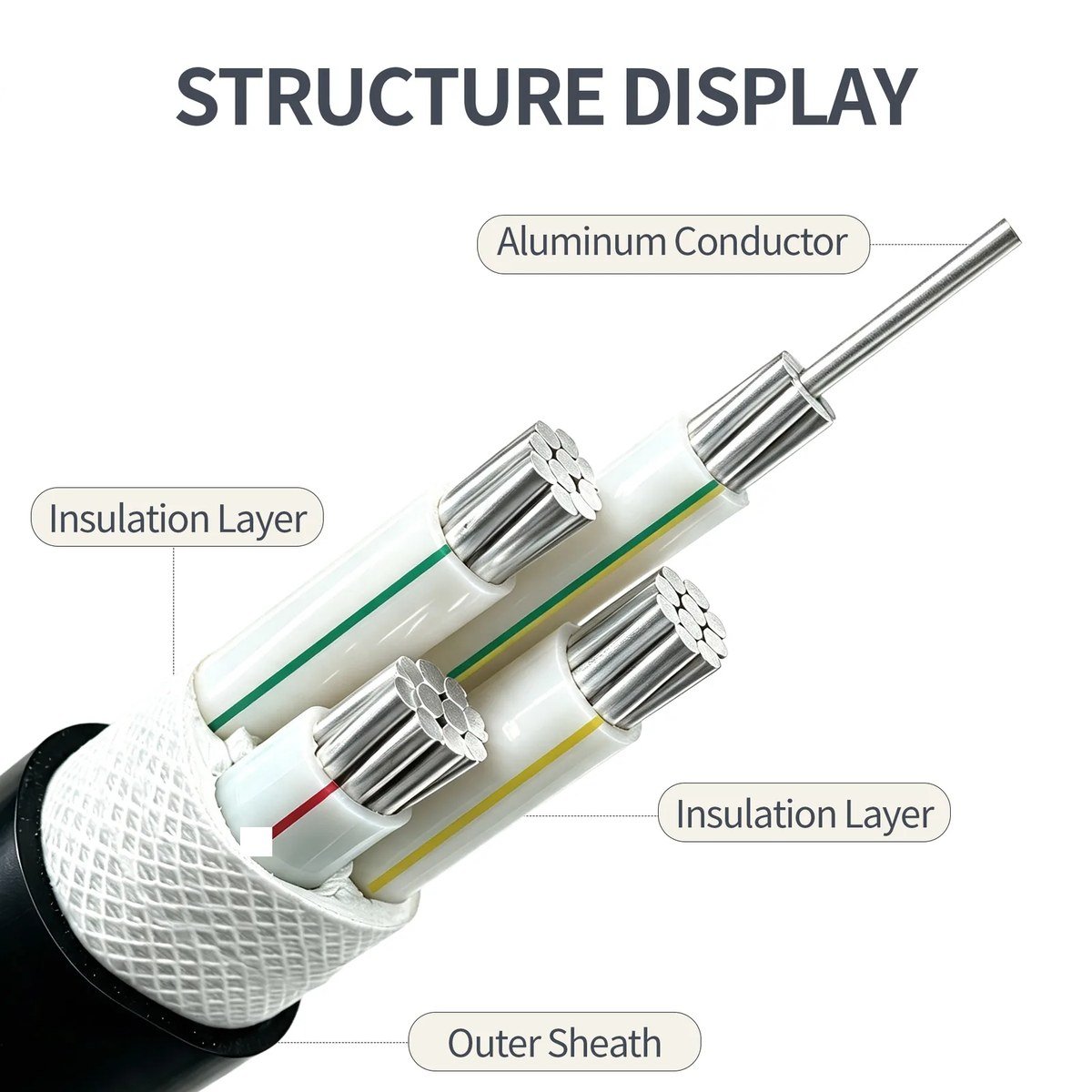
§01 — Cable construction
The reference construction, layer by layer.
At 19/33 kV (Uₘ 36 kV) the 8.0 mm insulation wall and the heavy bedding/armour package make this the largest three-core build in the MV range. Joint bay planning, drum lengths and pulling tensions are agreed before production, because every avoidable joint on a 33 kV route is a cost — both at installation and over the cable life.
| # | الطبقة | Reference detail |
|---|---|---|
| 01 | الموصل | Cu class 2 stranded (RM). Sector-shaped (SM) for 3-core ≥ 185 mm². |
| 02 | Conductor screen | Extruded semiconducting compound, ≤ 0.5 mm nominal thickness. |
| 03 | عزل XLPE | Extruded XLPE, 8.0 mm nominal at the 36 kV class (IEC 18/30 table; BS 6622 19/33 practice). |
| 04 | Insulation screen | Extruded semiconducting, strippable or bonded per requirement. |
| 05 | Metallic screen | Cu wire screen, 16–35 mm² by conductor size; for long 33 kV feeders the screen is verified against the full single-phase earth-fault duration. |
| 06 | Inner sheath | PVC ST2, extruded bedding. |
| 07 | الدرع | Double steel tape (STA) for direct burial; SWA for higher tensile load; AWA for single-core. |
| 08 | Serving | Anti-corrosion wrap on certain designs (optional). |
| 09 | Outer sheath | PVC ST2 black; PE or LSZH on request. |
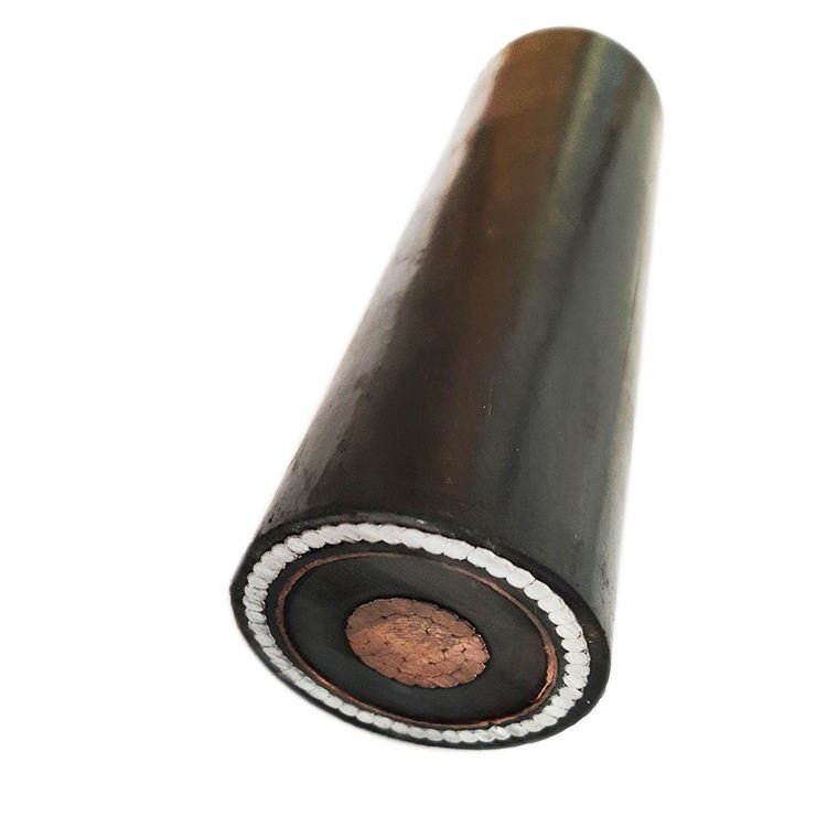
§02 — Technical specifications
Electrical parameters — 19 / 33 kV class.
| Conductor (mm² Cu) | Insulation thickness | DC resistance @20 °C (Ω/km) | Indicative current, direct burial 25 °C (A) |
|---|---|---|---|
| 3 × 35 | 8.0 mm | 0.524 | ~170 |
| 3 × 50 | 8.0 mm | 0.387 | ~205 |
| 3 × 70 | 8.0 mm | 0.268 | ~250 |
| 3 × 95 | 8.0 mm | 0.193 | ~300 |
| 3 × 120 | 8.0 mm | 0.153 | ~345 |
| 3 × 150 | 8.0 mm | 0.124 | ~385 |
| 3 × 185 | 8.0 mm | 0.0991 | ~435 |
| 3 × 240 | 8.0 mm | 0.0754 | ~500 |
| 3 × 300 | 8.0 mm | 0.0601 | ~560 |
| 3 × 400 | 8.0 mm | 0.0470 | ~640 |
DC resistance values per IEC 60228. Indicative current: ground 25 °C, soil thermal resistivity 1.5 K·m/W, depth 1.0 m, flat formation — reference only; final ampacity is calculated against your installation conditions. Overall diameter and weight for this voltage class are issued in the project datasheet with the formal offer.
§02B — Worked example · 19 / 33 kV
Conductor selection by short-circuit duty on a 33 kV primary feeder.
For a prospective fault of 25 kA with 1 s clearing: S ≥ I · √t / k = 25 000 / 143 ≈ 175 mm², so 185 mm² is the minimum Cu cross-section — independent of the load current. On real 33 kV routes the short-circuit figure, not ampacity, usually decides the conductor. Send the network fault data and we run both checks and state them in the datasheet.
§03 — Standards
Standards printed on the sheath and on the drum card.
§04 — Applications
Where 33 kV cable from Lulian is in service.
33 kV primary distribution
Bulk supply from grid substations to 33/11 kV zone substations in dense urban networks.
33 kV primary networks →Wind farm collection at 33 kV
Collector circuits in large onshore wind farms; single-core trefoil for long routes.
33 kV wind collection circuits →Steel & cement plant intake
33 kV direct intake for heavy industry with on-site step-down substations.
Heavy industry intake →Not sure which voltage class your network needs? See all cable applications and sector solutions, or send the system voltage and the earthing method — we confirm the class and the construction in the offer.
§05 — Quality testing
What we test on every drum.
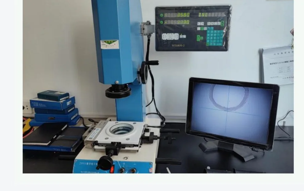
Routine tests run on every drum; sample tests on each batch; type tests on new constructions witnessed by CNAS-accredited third-party labs.
- Conductor DC resistance at 20 °C (routine)
- AC voltage withstand AC 66.5 kV / 5 min (routine)
- Partial discharge ≤ 10 pC at 32.9 kV (1.73 U₀) (sample)
- Insulation thickness & eccentricity (sample)
- Metallic screen cross-section (routine)
- Armour coverage & bedding integrity (routine)
- Sheath thickness + spark test (routine)
- Bending test + voltage after bending (type)
- Impulse voltage 170 kV (type)
§06 — Packaging & delivery
Drums sized for the cable, not for the workshop.
33 kV drums carry the routine test report on the drum card — including the 66.5 kV / 5 min withstand record — together with drum length and serial marking for joint-bay planning. Wooden drums with fumigation marks for export; steel-plywood drums for heavy cross-sections. Cable ends sealed with heat-shrink caps; shipping marks per the buyer’s format.
Standard drum lengths: 500 / 1000 / 1500 / 2000 m. Lead time: 25–35 working days for stocked constructions; 40–55 working days for project-specific builds.
§07 — FAQ
Common questions on 33 kV cable procurement.
What is the U₀/U rating of 33 kV XLPE cable?
19 / 33 kV, Uₘ = 36 kV per BS 6622 — the top of the MV range, equivalent to the IEC 18/30 (36 kV) class. For 35 kV systems we supply the 26/35 kV construction under GB/T 12706.3.
What conductor cross-sections are available?
Three-core: 25–400 mm². Single-core: 25–630 mm². Copper or aluminium, class 2 stranded; sector-shaped conductors for large 3-core sizes.
Can the cable be direct-buried?
Yes. The armoured construction (STA) with PVC ST2 outer sheath is rated for direct burial. SWA is recommended where tensile load or rodent risk is high.
What is the partial discharge limit?
≤ 10 pC measured at 32.9 kV (1.73 U₀) per IEC 60502-2. PD is measured on every drum and documented on the routine test report.
What routine and type tests are performed?
Routine on every drum: conductor DC resistance, AC voltage withstand AC 66.5 kV / 5 min, sheath spark test. Sample: PD, insulation thickness, screen check. Type: bending + voltage, load cycle, impulse voltage 170 kV.
Can the cable be supplied with LSZH sheath?
Yes, for tunnel, metro, data centre and indoor substation use. Verified against IEC 61034 (smoke density) and IEC 60754 (acid gas).
How are joint bays planned on a long 33 kV route?
Drum length decides the joint spacing, so we agree drum lengths against the route profile before production — typical lengths are 500–1 000 m on this class. Each drum is numbered against the joint-bay schedule and the pulling tension per section is stated in the installation notes.
أرسل جدول الكابلات. نؤكد التركيب خلال 24 ساعة.
Share voltage class, conductor material & size, core count, armour, sheath, installation method, total length and drum preference.
§08 — Related
Other voltage classes & adjacent products.
أرسل استفسارًا
اطلب عرض سعر
ثلاثة حقول. رد فني خلال 24 ساعة.