§01 — FEEDER DESIGN
Published 2026-09-24 · Engineering note
On short medium voltage runs the conductor is chosen by current-carrying capacity. On long runs it is almost always chosen by voltage drop instead, and the two answer can differ by two or three size steps. A 185 mm² copper cable that carries 300 A comfortably over 400 metres will fail a voltage drop check at 10 kilometres.
This note works through the arithmetic for an 11 kV feeder so you can see where the limit comes from, and what the practical options are when the cable alone cannot solve it.
§02 — THE FORMULA
Three-phase voltage drop
For a balanced three-phase load:
ΔU = √3 × I × L × (R·cos φ + X·sin φ)
ΔU is the line-to-line voltage drop in volts, I is the load current in amperes, L the route length in kilometres, R the conductor resistance at operating temperature in Ω/km, X the reactance in Ω/km. Taking the values at operating temperature rather than at 20 °C matters: for XLPE at 90 °C the resistance is roughly 1.27 times the 20 °C value.
Reactance depends on conductor spacing and cable geometry. For three-core armoured cable in the 6–35 kV range a figure around 0.08 Ω/km is a reasonable planning assumption; single-core cables in trefoil give a similar order. If the layout is unusual, ask for the design reactance rather than assuming.
§03 — WORKED EXAMPLE
10 km, 300 A, cos φ 0.9, 11 kV
Conditions: three-core XLPE, copper conductor, 11 kV (U₀/U = 6.35/11 kV), conductor temperature 90 °C, X = 0.08 Ω/km, cos φ 0.9 (sin φ 0.436). Resistance values are IEC 60228 class 2 maxima, converted to 90 °C.
| Conductor (mm²) | R at 20 °C (Ω/km) | R at 90 °C (Ω/km) | ΔU over 10 km (V) | ΔU (%) |
|---|---|---|---|---|
| 185 | 0.0991 | 0.126 | 772 | 7.0 |
| 240 | 0.0754 | 0.096 | 631 | 5.7 |
| 300 | 0.0601 | 0.077 | 539 | 4.9 |
| 400 | 0.0470 | 0.060 | 461 | 4.2 |
Same conditions for all four sizes. ΔU is line-to-line, so the percentage is taken against 11 000 V.
The result is uncomfortable. Even 400 mm² does not reach a 3 % drop over 10 km — it lands at 4.2 %. Going up a size helps, but the improvement from 185 to 400 mm² is only about 40 %, while copper content roughly doubles. Beyond a certain point you are buying metal to overcome distance, which is the wrong lever.
§04 — WHAT ACTUALLY FIXES IT
Three levers, in order of cost
Break the route
An intermediate switching station or a second infeed cuts the electrical length in half and the drop with it. Civil and switchgear cost is real, but it is usually cheaper than running 10 km of 400 mm² and still missing the target.
Raise the voltage class
Moving the feeder to 33 kV for the same power cuts the current by a factor of three, and the drop by roughly the same proportion. This is why long rural feeders tend to be built at 33 kV and stepped down at the load.
Increase the section
Useful for the last few percent. Check the short-circuit withstand at the same time — a larger conductor changes the thermal duty and the screen requirement.
Two checks that are easy to forget. First, the drop is calculated at maximum demand, which is not the same as the sum of connected load — applying diversity properly can remove the apparent need for a larger cable. Second, the operating temperature assumption matters: if the cable never actually reaches 90 °C, using 90 °C resistance overstates the drop, and using 20 °C understates it. State the assumption in the design record.
§05 — ORDERING
What to put in the enquiry
If you send an enquiry for a feeder like the one above, the supplier cannot quote correctly without the route length, the maximum demand current, the power factor, the system voltage and the earthing arrangement. Length also drives the drum plan: 10 km of three-core 400 mm² cannot be delivered on one drum, so the joint positions become part of the design.
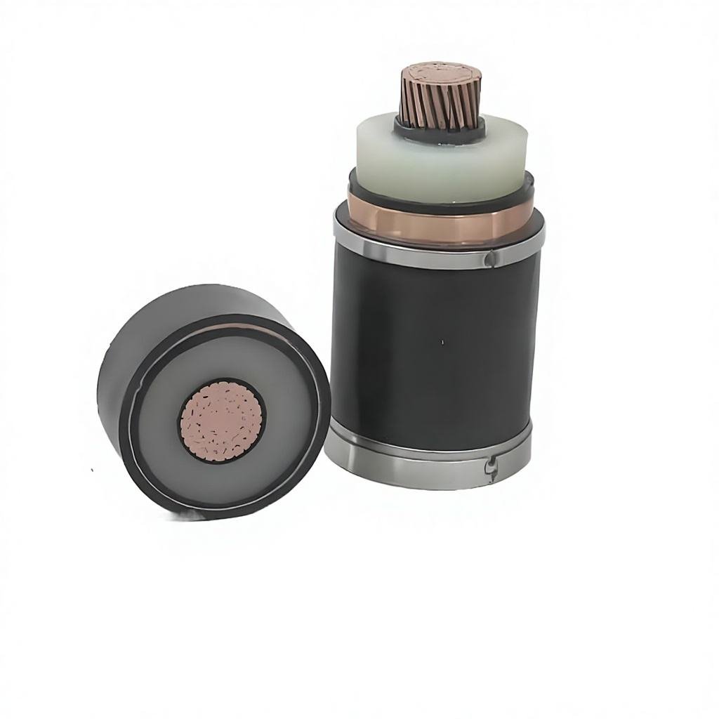
Our medium voltage cable range from 6 kV to 35 kV covers the sections used in this example. The 11 kV XLPE cable page carries the full construction and test data for the 6.35/11 kV class, and the 11 kV distribution application brief walks through a 22 km urban case including the switching station decision.
§06 — أسئلة شائعة
Questions this raises
Is 0.08 Ω/km reactance accurate enough for design?
For three-core armoured cable in this voltage range it is a reasonable planning figure and is commonly used at concept stage. Once the cable construction is fixed, use the manufacturer’s published reactance for the detailed calculation. The difference between 0.07 and 0.10 Ω/km changes the result by roughly 5 % at cos φ 0.9.
Why is resistance quoted at 90 °C rather than 20 °C?
Because the conductor is at operating temperature when the drop matters. XLPE is rated for a 90 °C continuous conductor temperature, and copper resistance rises by about 0.39 % per degree, so the 20 °C tabulated value understates the drop by around 27 %.
Can aluminium be used instead of copper?
Yes, but aluminium resistivity is about 1.64 times copper, so you need roughly two size steps more to reach the same resistance. On a voltage-drop-limited feeder that is usually uneconomic; on a shorter feeder where ampacity governs, aluminium is often the right answer.
Does the drop limit apply to the cable or to the whole feeder?
To the whole feeder, including transformers, joints and any series equipment. The cable calculation above is only the cable share. If the total feeder budget is 3 % and the cable takes 4.2 %, resizing the cable alone will not get you there.
How does this change for single-core cable?
Reactance is lower because the conductors are closer in trefoil than in a three-core laid-up assembly, typically enough to reduce the reactive term by 10–20 %. Resistance is unchanged for the same section. Single-core armoured cables also need a non-magnetic armour such as aluminium wire, which is a separate selection point.