§01 — INSTALLATION
Published 2026-09-24 · Engineering note
Installation limits get treated as a contractor’s problem, and then the tender comes back with a price for larger manholes or an extra joint chamber. In practice three numbers — minimum bending radius, maximum pulling tension and maximum sidewall pressure — are decided when the cable construction is chosen, and they are difficult to change afterwards. They belong in the specification.
§02 — BENDING RADIUS
Set by construction, not by voltage
IEC 60502-2 does not fix an installation bending radius; the manufacturer states it for each construction. What drives it is whether the cable is armoured and whether it is single-core or multi-core, because those determine how the layers move when the cable is bent.
| Конструкция | Typical minimum bending radius | Why |
|---|---|---|
| Unarmoured, single-core | 20 × D | No armour to hold the sheath; the screen and insulation layers carry the strain |
| Unarmoured, multi-core | 15 × D | Laid-up cores support each other |
| Armoured, single-core | 15 × D | Armour adds stiffness and resists ovality |
| Armoured, multi-core | 12 × D | Armour plus a circular core assembly |
D is the overall cable diameter. These are typical industry values for the purposes of pre-design. Always use the figure published for the specific construction you are buying — a large three-core cable and a small control cable obey the same principle but not the same multiple.
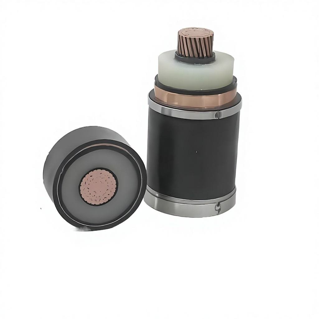
The consequence is geometric. A 400 mm² three-core armoured cable has an overall diameter in the region of 95 mm; at 12 D that is a 1.14 m radius, or 2.28 m across. A cable chamber or duct bend drawn at 1.5 m across will not accept it. This is worth checking at drawing stage rather than at delivery.
§03 — PULLING TENSION
The conductor is the limiting element
During a pull, the force is applied to the conductor or to a pulling eye bonded to it, so the conductor cross-section sets the limit. The usual planning values are 50 N/mm² for copper and 30 N/mm² for aluminium. For a 185 mm² copper conductor that is 9 250 N; for 240 mm² it is 12 000 N.
Whether that is enough depends on route length, weight, duct friction and the number of bends. A first estimate for a straight duct pull:
T = μ × W × L
where μ is the friction coefficient (0.3–0.5 for a cable in a duct is a normal planning range, higher if the duct is dirty or offset), W the cable weight per metre, and L the pull length. Bends multiply the figure: each bend adds a multiplier that depends on the angle and the friction coefficient, and three or four bends in a run is where estimates usually go wrong.
Two practical points. First, pulling lubricant is not a detail — it changes μ by a large factor and is cheaper than a larger conductor. Second, if the calculated tension approaches the conductor limit, the answer is usually an intermediate pull or a joint chamber, not a bigger cable.
§04 — SIDEWALL PRESSURE
The check people skip
Force per unit length on the bend
At a bend, the pulling tension presses the cable against the inside of the duct. The pressure is the tension divided by the bend radius: P = T / R.
It crushes the cable, not the conductor
Conductor tensile strength says nothing about this. Excessive sidewall pressure deforms the insulation and screen, and the damage is invisible from outside.
Around 3 kN per metre of bend
Commonly used planning value for this class of cable. Larger bends are less severe; tight bends at full tension are the dangerous combination.
The arithmetic explains why tight bends near the end of a long pull are the worst case: tension is at its highest and radius at its lowest, so the two effects multiply. Increasing the bend radius is usually cheaper than reducing tension, which means it is a duct-laying decision made before the cable is ordered.
§05 — TEMPERATURE
Cold-weather installation
Sheath compounds stiffen as they cool, and below a certain temperature the cable should not be bent or pulled without pre-warming. PVC sheaths are generally not to be handled below about 0 °C; XLPE insulated cables with PE or LSZH sheaths are typically workable down to around −20 °C, but the figure depends on the sheath compound, not the insulation. For projects scheduled in winter or in cold climates, state the expected installation temperature in the enquiry so the sheath compound can be matched to it. Pre-warming the drum and working in short sections is the usual mitigation, but it requires the right compound to work at all.
These are planning values for pre-design. The published installation instructions for the specific cable govern, and they should be on site before the pull starts.
§06 — ORDERING
What to put on the drawing
Minimum bending radius, maximum pulling tension and maximum sidewall pressure all come from the construction, so they should be stated in the enquiry along with the route. Sending a route drawing with duct sizes, bend radii and manhole positions allows the construction to be chosen to suit the installation rather than the installation being adapted to whatever arrives.
The 6–35 kV medium voltage range covers armoured and unarmoured constructions in single-core and three-core. Construction and test data for the 6.35/11 kV class is on the 11 kV XLPE cable page. For buried work where mechanical protection decides the armouring, the armoured power cable page covers the steel tape and steel wire options and the direct-burial rules.
§07 — FAQ
Questions this raises
Should the bending radius be quoted for the drum or for installation?
They are different figures. Drum diameter controls how tightly the cable is stored; the installation radius is what applies during the pull and in service. Both should be published, because a drum that is too small for the construction causes the same damage as a tight bend.
Can the cable be pulled by the armour instead of the conductor?
No. Pulling on the armour loads the armour wires in tension and can displace them or tear the sheath. The pull is taken on the conductor via a pulling eye, or on a stocking grip combined with a pulling eye for the conductor, with the armour gripped only to guide the cable.
How many bends are acceptable in one pull?
There is no single number — it depends on the angle, the friction coefficient and the ratio of tension to sidewall limit. A route with three 45° bends is lighter than one with two 90° bends. The calculation, not a rule of thumb, should decide, and the calculation needs the actual duct geometry.
Does the same limit apply to triplex or trefoil single-core installations?
The bending radius principle is the same, but single-core cables in trefoil are individually smaller and easier to handle, and their screen construction adds a constraint: repeated tight bending can damage the copper wire screen at the point where it wraps. Follow the published figure rather than deriving one from the conductor size.
What if the site temperature is below the cable’s rated installation limit?
Options are pre-warming the drum and pulling in short sections, or selecting a sheath compound rated for lower temperature. Pre-warming only helps if the compound itself is suitable — it raises the temperature temporarily rather than changing the material.