
§01 — INSULATION QUALITY
Published 2026-09-24 · Engineering note
Ask a cable supplier for test data and you will usually get a withstand test result. That test tells you the insulation did not break down at the applied voltage for five minutes. It does not tell you whether there is a void inside the insulation that will grow for the next fifteen years. Partial discharge measurement is what covers that gap, which is why it is a routine test on every length of medium voltage cable rather than a sample test.
§02 — THE PHENOMENON
Discharge that does not bridge the insulation
Partial discharge is an electrical discharge that occurs within or on the surface of an insulation system without completely bridging the electrodes. It happens where the local electric field exceeds the breakdown strength of a small volume — most often a gas-filled cavity in the insulation, a sharp protrusion on a semi-conductive screen, or contamination at an interface.
Each discharge transfers a small amount of charge, measured in picocoulombs. The damage per event is negligible. The problem is that the discharge erodes the cavity wall, the cavity grows, and the process accelerates: this is the mechanism behind electrical treeing, and it ends in breakdown. A cable that passes a withstand test with an active discharge site is a cable with a known failure mechanism installed in it.
§03 — THE LIMIT
Why 10 pC at 1.73 U₀
IEC 60502-2 requires a routine partial discharge test on every length of medium voltage cable, with the discharge magnitude not exceeding 10 pC at a test voltage of 1.73 U₀. The 1.73 is √3, so the test voltage is the phase-to-phase voltage of the system, applied to the insulation that normally sees phase-to-earth voltage.
| Класс напряжения | U₀ (kV) | PD test voltage 1.73 U₀ (kV) |
|---|---|---|
| 3.6/6 кВ | 3.6 | 6.2 |
| 6/10 кВ | 6.0 | 10.4 |
| 6.35/11 кВ | 6.35 | 11.0 |
| 8.7/15 кВ | 8.7 | 15.1 |
| 12/20 кВ | 12.0 | 20.8 |
| 19/33 кВ | 19.0 | 32.9 |
| 26/35 кВ | 26.0 | 45.0 |
Test voltage is 1.73 times U₀, the rated phase-to-earth voltage. The 10 pC limit is the routine test requirement for the constructions covered by IEC 60502-2.
Why 10 pC rather than zero? At some level every measurement system has noise, and no manufacturing process is perfectly void-free. Ten picocoulombs is the level that experience has shown can be achieved consistently by a controlled process while remaining low enough to exclude defects that would grow. It is a process capability limit as much as an electrical one.
§04 — MEASUREMENT
How the number is obtained
The test methods are set out in IEC 60270. In practice the length under test is energised at 1.73 U₀, held while the discharge activity is measured, then the voltage is reduced and the measurement repeated to confirm the reading is repeatable rather than a transient artefact. The measurement is calibrated by injecting a known charge pulse at the start of the test, so the picocoulomb figure is traceable to the calibration rather than being an instrument reading.
Cavities in the insulation
Gas pockets trapped during extrusion or formed by shrinkage. Controlled by compound quality, temperature profile and degassing.
Screen protrusions
Sharp points or irregularities on the conductor screen or insulation screen concentrate the field. The reason triple extrusion matters.
Interfaces and terminations
Contamination at layer boundaries, and — at site level — poorly made terminations and joints. A cable can pass in the factory and discharge after installation.
§05 — WHAT IT TELLS A BUYER
Reading the number
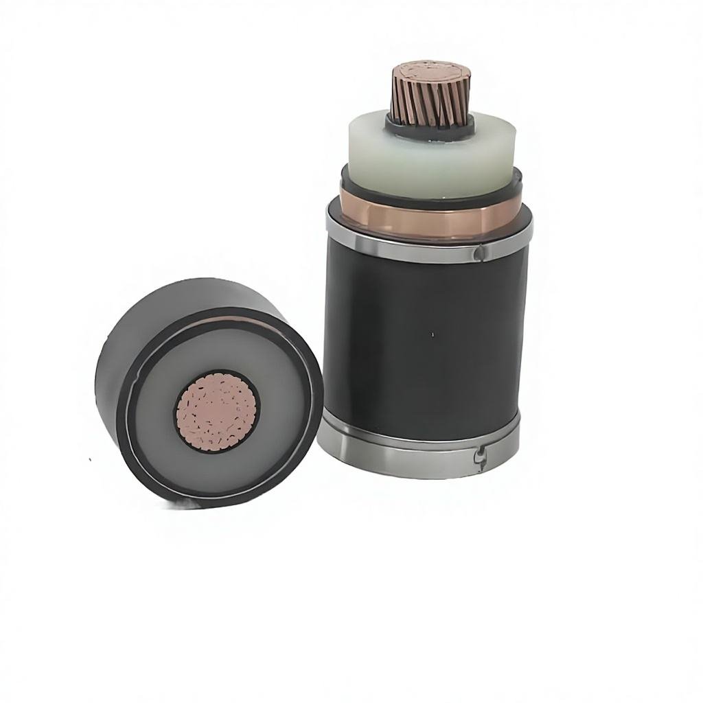
A routine PD test result on every length is a statement about process control. Three-layer simultaneous extrusion — conductor screen, insulation and insulation screen applied in one pass without an intermediate interface exposed to air — is the main construction measure that keeps cavity and protrusion sources under control. Without it, the interfaces between separately applied layers are the weak point, and the PD result reflects that.
The number to ask for is the measured value, not a pass statement. A length that measures 2 pC and one that measures 9.9 pC both pass the standard, and they do not represent the same manufacturing outcome. A plant that publishes measured values across a range of lengths is telling you something more useful than one that publishes a tick.
Installation matters as much as manufacture. A factory-tested cable can discharge after a badly assembled termination or joint. The routine test result is evidence about the cable, not about the finished circuit.
§06 — ORDERING
What to ask for
Ask for the routine test record for the actual lengths shipped, including the measured partial discharge value and the test voltage, not only the withstand result. Where a project specifies a tighter limit than the standard — some utilities do — state it in the enquiry so the test is planned and the lengths are allocated accordingly.
Construction and routine test detail for the 6.35/11 kV class is on the 11 kV XLPE cable, routine tested to ≤ 10 pC; the same test regime applies across the 6–35 kV medium voltage range. The layer arrangement that determines most of the PD performance is described on the medium voltage construction page, and the wider test regime including flame and smoke performance is covered in the certificate and test documentation section.
§07 — FAQ
Questions this raises
Is 10 pC the same limit for all voltage classes?
The requirement is expressed as a magnitude limit rather than a percentage of something else, so 10 pC applies across the classes covered. What changes with voltage is the test voltage: 11.0 kV for a 6.35/11 kV cable, 45.0 kV for a 26/35 kV cable. At higher voltages a given defect tends to produce a larger discharge, so the same limit is harder to achieve, which is why higher-voltage construction and process control are more demanding.
Does passing the PD test mean the cable will not fail in service?
No. It means the length as tested contained no discharge site above 10 pC at 1.73 U₀, which excludes the most likely manufacturing defects. Failures in service are usually traced to installation — terminations, joints, mechanical damage, water ingress at a damaged sheath — rather than to a defect that passed the routine test.
Why is the test done at 1.73 U₀ rather than at the operating voltage?
Because a defect that is marginal at operating voltage needs a margin to be detectable and to represent a safety factor. √3 is the ratio between phase-to-phase and phase-to-earth voltage, so testing at 1.73 U₀ stresses the insulation by the same factor that would appear if the system were to run at its highest phase-to-phase level relative to earth.
Can I get the discharge value for each drum?
The test is a routine test on every length, so the records exist per length. Whether they are supplied per drum depends on the order agreement. For projects where the requirement is tight, specify that the measured value for each length is to be included in the test documentation, and check that what arrives matches what was ordered.
What about the withstand test — is it still needed?
Yes, they check different things. The withstand test applies 3.5 U₀ for five minutes and confirms the insulation does not break down under overvoltage. The PD test detects defects that do not break down but would grow. A cable with an active void passes the withstand and fails the intent of a good insulation system.