§01 — PROTECTION
Published 2026-09-24 · Engineering note
A cable that carries the load current and passes the voltage drop check can still be wrong. If a fault occurs at the near end of the feeder and the protection takes a second to clear it, the conductor has to survive that second without being damaged. This is usually the constraint that sets the minimum section on feeders close to a substation, in the same way voltage drop sets it on long rural routes.
§02 — THE CHECK
Adiabatic short-circuit check
The standard approach treats the fault duration as too short for heat to escape, so all the energy stays in the conductor:
S ≥ (I × √t) / k
S is the required conductor cross-section in mm², I the prospective fault current in amperes, t the protection clearing time in seconds, and k a material and insulation constant. The formula is the adiabatic method; for longer durations or very large sections the non-adiabatic method in IEC 60949 gives a slightly lower requirement.
k values in common use
| Conductor | Aislamiento | k | Initial / final temperature |
|---|---|---|---|
| Copper | XLPE | 143 | 90 °C / 250 °C |
| Copper | PVC | 115 | 70 °C / 160 °C |
| Aluminium | XLPE | 94 | 90 °C / 250 °C |
| Aluminium | PVC | 76 | 70 °C / 160 °C |
Values as tabulated in IEC 60364-5-54. Where a conductor is also a protective conductor, or where joints are involved, confirm the applicable value — a joint is often the thermal weak point.
§03 — WORKED CHECK
26 kA for one second, 11 kV feeder
Prospective fault current 26 kA, protection clears in 1 s, XLPE insulated copper cable.
S ≥ (26 000 × √1) / 143 = 182 mm²
The next standard section is 185 mm², so a 185 mm² copper XLPE cable just passes. Two things follow from that. First, the margin is nil — any increase in fault level or clearing time pushes the requirement above 185 mm². Second, the same feeder in aluminium would need 26 000 / 94 = 277 mm², so 300 mm², which is a two-step jump for the same duty.
Because I²t is what matters, the check scales predictably. If the same 26 kA is cleared in 0.5 s instead of 1 s, the requirement falls to 26 000 × √0.5 / 143 = 129 mm². Faster protection is worth more than copper. This is why the fault level and the protection settings belong in the cable enquiry, not just the load current.
§04 — THE SCREEN IS A SEPARATE CASE
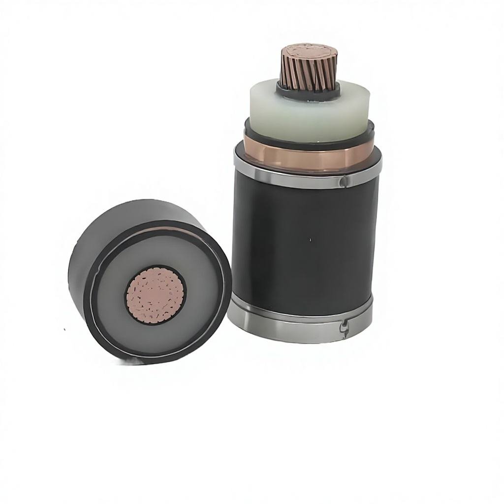
What the copper wire screen does under fault
Electric field control
The screen holds the outer surface of the insulation at earth potential, which is what makes the field within the insulation predictable. Remove it or make it discontinuous and the design assumptions no longer hold.
Fault current path
In a single-core cable bonded at both ends, the screen carries induced current during normal operation and a share of the fault current during a fault. Both are thermal duty on a section that is much smaller than the conductor.
Earth fault return
On many distribution networks the screen is the earth fault return path. Its section then has to be checked against the earth fault current and duration, not the three-phase fault.
The screen section is specified in IEC 60502-2 for the relevant construction, and the thermal duty is assessed using the short-circuit temperature rise method in IEC 60949 with the screen’s own starting temperature and permissible final temperature. Because the screen has far less copper than the conductor, it reaches its limit sooner — a screen that is adequate for the three-phase fault can be inadequate for a sustained earth fault on a single-end-bonded section. If your network relies on the screen as the fault return, say so in the enquiry so the construction is selected for it rather than defaulted.
This is also where earthing arrangement stops being an installation detail and becomes a cable specification item. Single-point bonding, cross-bonding and both-end bonding give different screen duties and different permissible lengths.
§05 — ORDERING
Information the supplier needs
Four numbers determine the answer: prospective fault current, protection clearing time, system voltage and earthing arrangement. Load current and route length are separate checks that run alongside. Without the first four, a supplier can only quote a plausible cable rather than the correct one.
The 6–35 kV medium voltage range lists conductor sections and screen constructions by voltage class. Detailed construction and test data for the 6.35/11 kV class is on the 11 kV XLPE cable page, and the 19/33 kV class is covered on the 33 kV page. If the feeder also has a long route, check voltage drop before fixing the section — the two checks sometimes point at different sizes.
§06 — Preguntas frecuentes
Questions this raises
Which fault current should be used — three-phase or earth fault?
Both, because they load different parts. The three-phase fault current sets the conductor requirement. The earth fault current sets the screen or armour requirement where those form the return path. On solidly earthed networks the earth fault current can be the larger of the two.
Does the check change if the cable runs in a duct or in air?
Not for the adiabatic short-circuit check, because heat is assumed not to escape during the fault. Installation method affects the continuous current rating, which is a separate calculation.
What about joints?
A joint is a thermal discontinuity and is often the limiting element rather than the cable. Where the fault level is close to the cable limit, ask for the joint rating as well, and consider whether the joint position can be moved away from the high-fault end of the feeder.
Is 250 °C permissible final temperature realistic for XLPE?
It is the short-circuit value used in the standard, not a continuous rating. XLPE is rated 90 °C continuous. The 250 °C figure applies only for the duration of the fault and assumes the cable is not required to carry load again until it has cooled back to its normal operating temperature.
How does this interact with voltage drop sizing?
They are independent limits and the larger governs. A feeder near a substation is usually limited by short-circuit withstand; a long rural feeder is usually limited by voltage drop. When a site needs both a large section for drop and a large screen for fault return, the construction should be selected for both explicitly rather than assumed.