
Cable de media tensión
6–35kV Medium Voltage XLPE Cable
Medium-voltage XLPE cable for utility, substation, renewable-energy, infrastructure and industrial distribution projects.
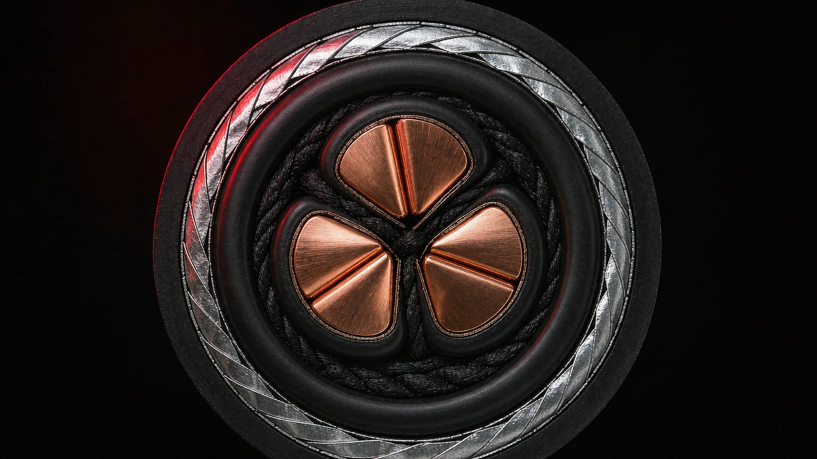 3-core Cu · XLPE · steel-wire armour
PRODUCT GALLERY
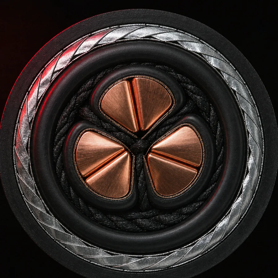
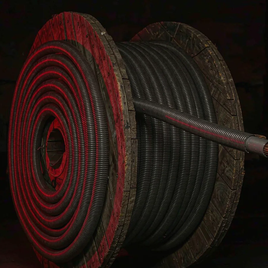
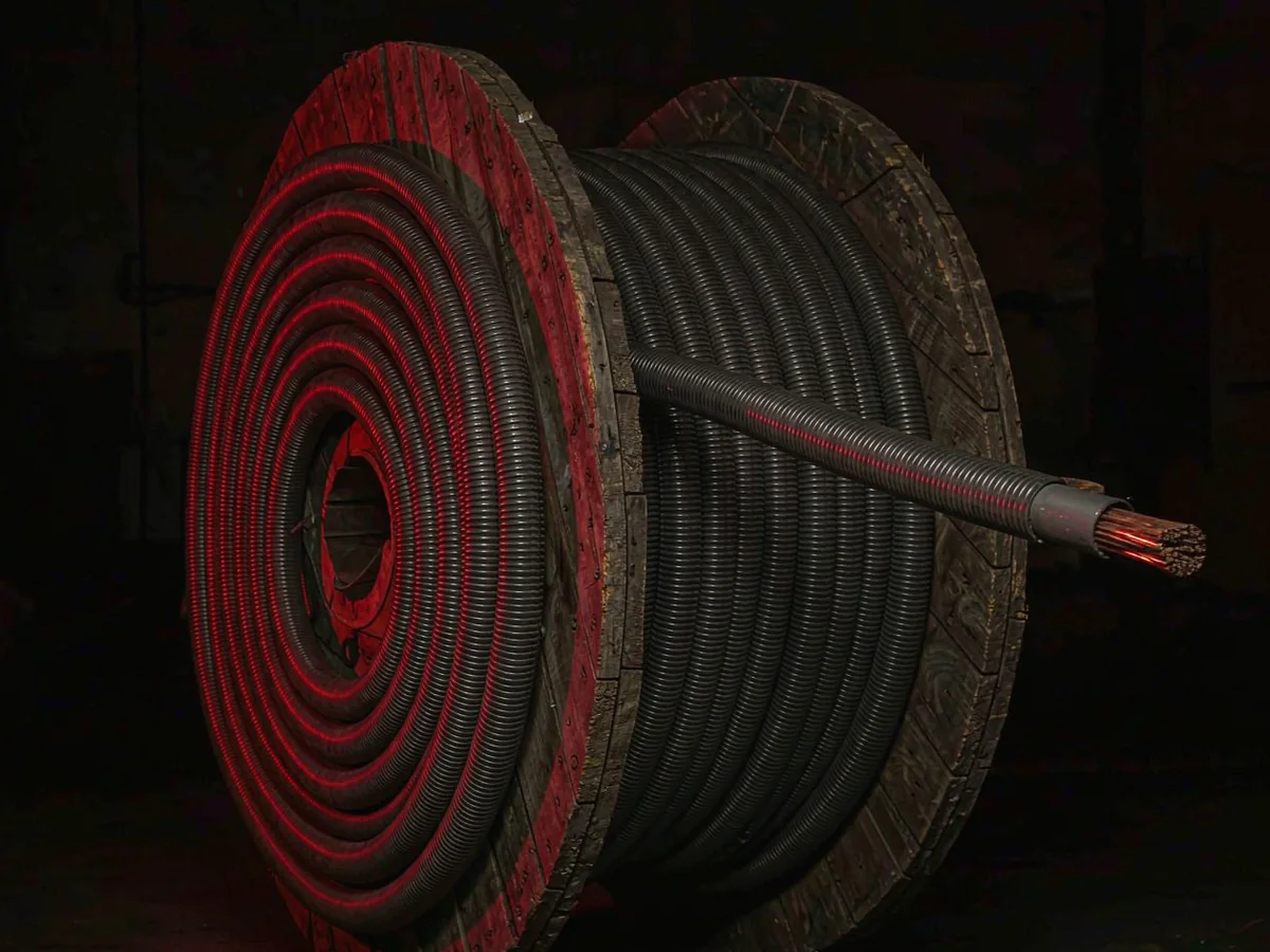
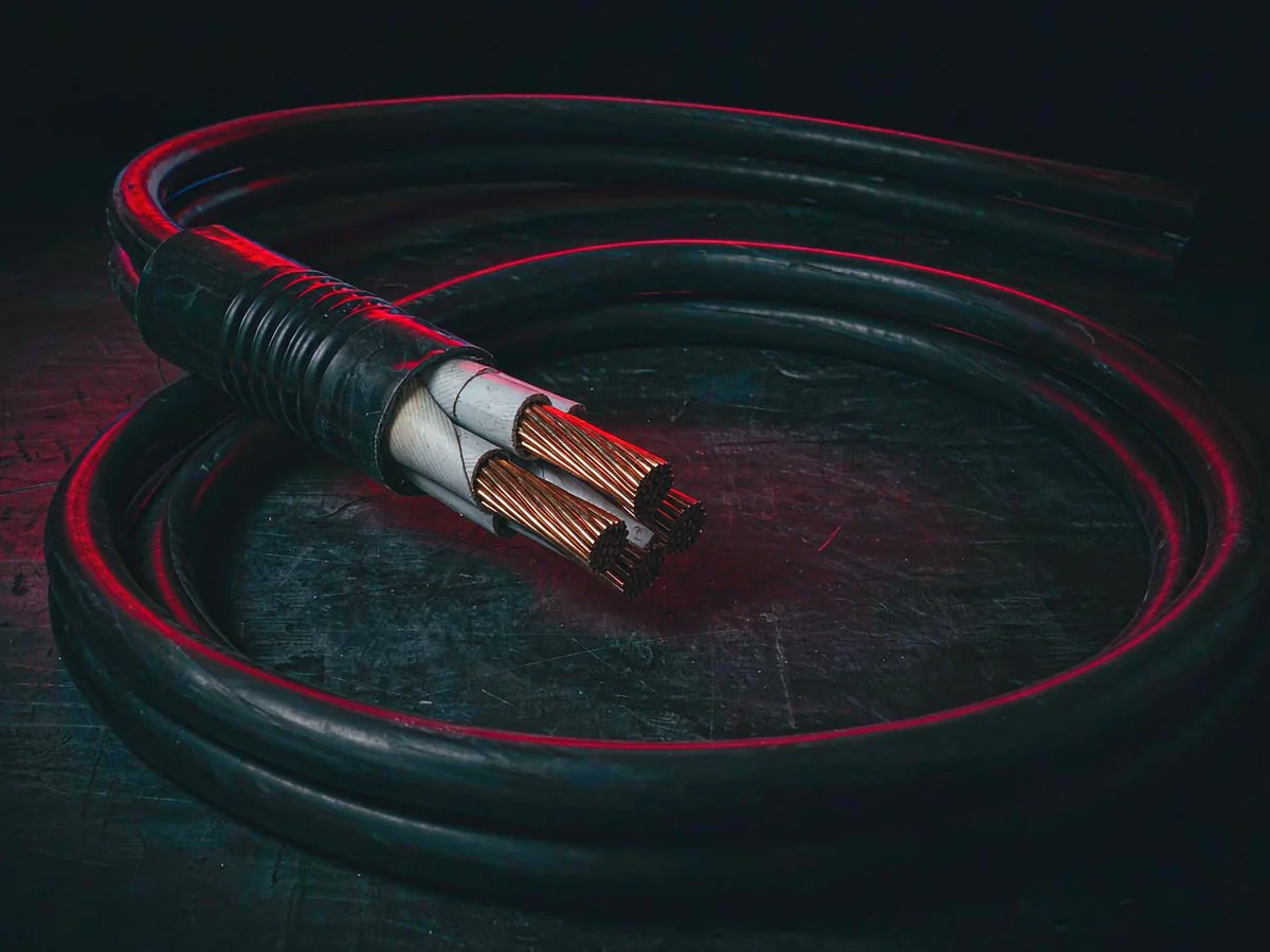
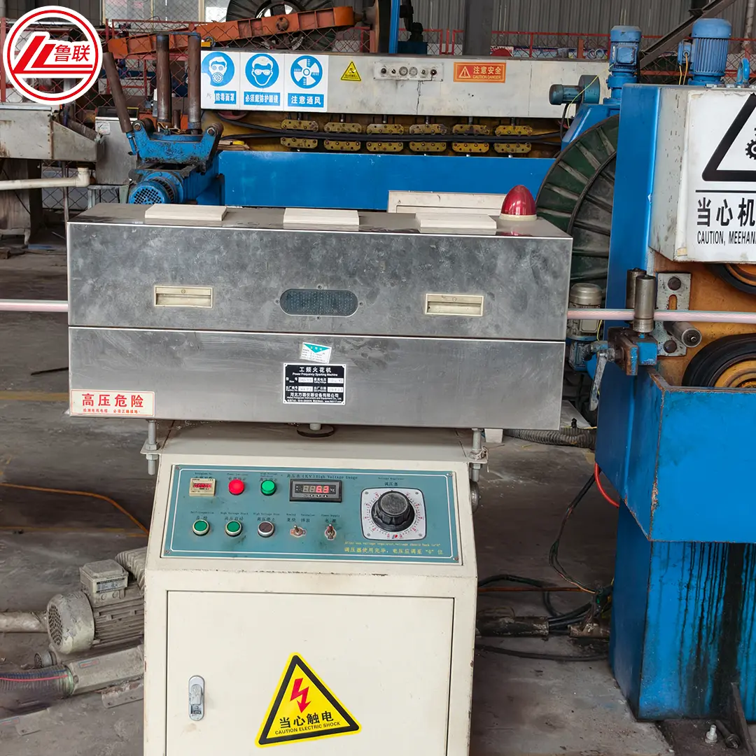
The process in pictures: every layer, every drum.
PRODUCT OVERVIEW
Every voltage class is confirmed against your system conditions.
- Voltage classes — 6, 10, 15, 20 and 35 kV; each design confirmed for system voltage, insulation screen, metallic screen and installation conditions.
- Conductor — Class 2 copper or aluminum, compacted for lower skin effect at MV.
- Screen system — conductor screen, XLPE insulation, insulation screen, copper wire or tape metallic screen.
- Protection — water-blocking layers; unarmored, steel-tape or steel-wire armor; PE, PVC or LSZH sheath.
- Standards — IEC 60502-2 · GB/T 12706.2/3 · IEC 60228, as specified.
CONSTRUCTION, LAYER BY LAYER
From conductor to outer sheath: the four layers, explained.
Conductor
Class 2 compacted copper or aluminum, IEC 60228. Sector-shaped for 3-core designs.
Aislamiento
Dry-cured XLPE with conductor and insulation screens; smooth interface keeps partial discharge low.
Metallic screen
Copper wire or tape screen, cross-section sized to the system fault requirement.
Armour & sheath
Steel-tape or steel-wire armor for the route; PE, PVC or LSZH outer sheath as specified.
WHERE THIS CABLE GOES
Choose the voltage by application, not by guesswork.
Distribución de redes
12/20 – 26/35 kV
Primary feeders and ring mains; STA armor for direct burial, SWA for pulled routes.
Industrial plants
3.6/6 – 8.7/15 kV
MV motors 200 kW–10 MW and plant intakes; LSZH sheath for indoor trays.
Solar & wind collection
19/33 – 26/35 kV
Power-plant collector circuits from station transformer to the grid connection.
SELECTION PARAMETERS
Selection parameters.
| Tensión nominal | 6/10kV, 8.7/15kV, 12/20kV, 18/30kV or 26/35kV, as specified |
|---|---|
| Conductor | Class 2 copper or aluminum conductor |
| Core options | Single-core or three-core construction |
| Screen system | Conductor screen, XLPE insulation, insulation screen and metallic screen |
| Armor | Unarmored, steel-tape or steel-wire construction selected for the installation route |
| Outer sheath | PVC, PE or LSZH compound as specified |
| Applicable standards | IEC 60502-2 · GB/T 12706.2/3 · IEC 60228, as specified |
| Quotation data | Voltage, conductor, cores, cross-section, screen, armor, sheath, length and destination |
Discuss Your Cable Requirements
Send your specification, quantity and destination. Our team replies within one business day.