
Cable armado de tres núcleos 11 kV para una extensión de distribución urbana de 22 km
How a typical 11 kV utility extension project moves from cable schedule to delivered drums: the installation conditions, the selection logic, the engineering risks and the quality checkpoints. Written from our standard production and export workflow.
§01 — Project background
A utility extends an 11 kV ring to a new industrial zone.
A distribution utility plans a 22 km 11 kV feeder extension from an existing 33/11 kV zone substation to a new light-industrial zone. The route follows public road verges with several road crossings in ducts, plus a 400 m section across agricultural land. The utility’s specification calls for three-core copper cable, steel tape armour, and routine test documentation per drum.
This brief is a typical engineering scenario based on our standard 11 kV production and export workflow. It does not describe a specific client contract; no client names, project names or contract values are claimed.
§02 — Installation conditions
What the route looks like before the cable is chosen.
| Parámetro | Condition | Design impact |
|---|---|---|
| Método de instalación | Direct burial in verge + 6 road crossings in ducts | STA armour required; duct sections derate ampacity ~10 % |
| Soil thermal resistivity | 1.2 K·m/W (design assumption; confirm by on-site measurement) | Sets the ampacity baseline; higher resistivity forces larger cross-section |
| Ground temperature | 25 °C design | Standard rating conditions |
| Burial depth | 1.0 m to top of cable | Norma |
| Load profile | 2.5 MVA continuous, peak 3.2 MVA 2 h | Determines conductor cross-section |
| System earthing | Resistance-earthed, earth-fault factor 1.4 | U₀ = 6.35 kV class acceptable (6.35 × 1.73 ≥ 11) |
| Fault level | 18.4 kA / 1 s at the intake | Metallic screen cross-section check (≥ 16 mm² Cu adequate) |
§03 — Cable selection logic
Why 3 × 185 mm², and not 240 mm².
- Current requirement: 3.2 MVA at 11 kV ≈ 168 A. A 185 mm² three-core Cu cable at reference conditions carries ~435 A — comfortable margin even after duct-section and grouping derating.
- Voltage drop: over 22 km at 168 A, R = 0.0991 Ω/km, ΔV ≈ 168 × 0.0991 × 22 × √3 ≈ 634 V ≈ 5.8 % — above the usual 5 % limit for the full run, so the utility splits the feeder with a mid-point switching station. This is a system design decision, not a cable limitation.
- Short-circuit: 185 mm² Cu withstands ~26 kA for 1 s (adiabatic, k = 143) — above the 18.4 kA system fault level.
- Why not 240 mm²: +30 % copper cost for margin the duty does not need. The mid-point switch resolves the voltage drop more economically.
§04 — Cable construction
The specified build.
| Capa | Specification |
|---|---|
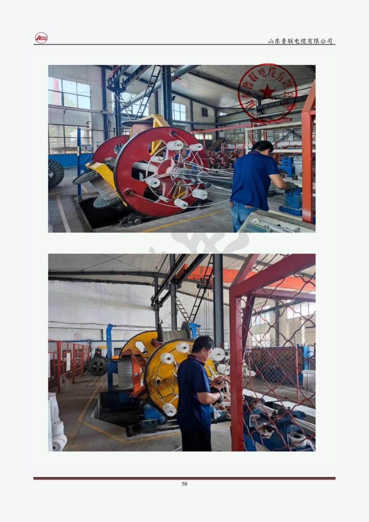
| Conductor | Copper class 2 stranded compact (RM), 3 × 185 mm² |
| Conductor screen | Extruded semiconducting |
| Aislamiento | XLPE, 3.4 mm nominal (IEC 60502-2 for 6.35/11 kV) |
| Insulation screen | Extruded semiconducting, strippable |
| Metallic screen | Copper wire screen, ≥ 16 mm² per core |
| Bedding | PVC ST2 extruded |
| Armadura | Double steel tape (STA), galvanized |
| Outer sheath | PVC ST2, black, red stripe per utility marking convention |
§05 — Key engineering risks & how they were controlled
Partial discharge at screen interfaces
Controlled by triple-extrusion + dry curing CCV; PD ≤ 10 pC at 1.73 U₀ measured on every drum before it leaves the factory.
Armour damage during pulling into ducts
Drum sizing keeps bending radius ≥ 12 × OD; pulling eyes and swivel specified; duct sections pre-lubricated per installation manual shipped with drums.
Moisture ingress at cut ends during transit
Both cable ends sealed with heat-shrink end caps; drums stored upright; end seal check part of pre-shipment inspection.
§06 — Quality control & testing
What gets measured before the drums ship.
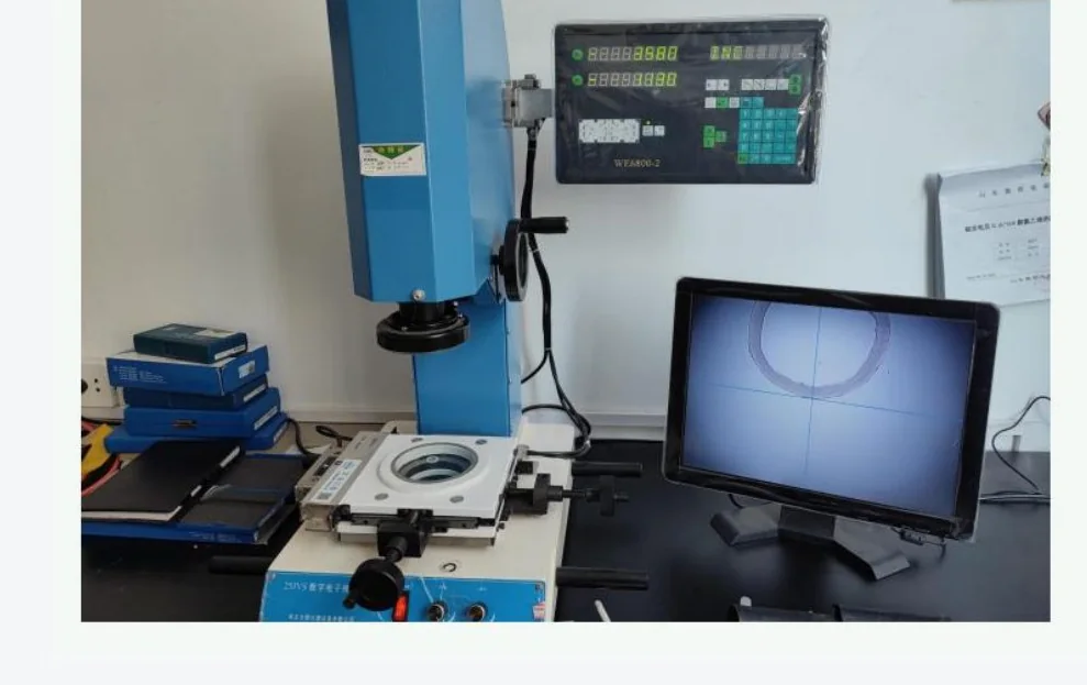
- Conductor DC resistance at 20 °C — every drum (≤ 0.0991 Ω/km for 185 mm²)
- AC voltage withstand 22 kV / 5 min — every drum
- Partial discharge ≤ 10 pC at 11 kV (1.73 U₀) — sample per batch
- Insulation thickness & eccentricity — sample
- Metallic screen cross-section — every drum
- Sheath thickness + spark test — every drum
- Drum condition, end seals, marking — pre-shipment check
§07 — Packing & delivery
Twenty-two kilometres on eleven drums.
11 × 2000 m lengths on fumigated wooden drums sized to the cable OD (drum flange ≥ 25 × OD bending rule). Each drum: heat-shrink end caps both ends, waterproof wrap, drum card with construction, length, gross weight, routine test values and shipping marks per the buyer’s format. FOB Qingdao, 40′ open-top or flat-rack as required.
§08 — RFQ checklist for a similar project
Copy this list into your inquiry — we return a confirmed construction in 24 h.
| Elemento | Example entry |
|---|---|
| System voltage / earthing | 11 kV, resistance-earthed, EFF 1.4 |
| Load / voltage-drop limit | 2.5 MVA cont., 3.2 MVA peak 2 h, ΔV ≤ 5 % |
| Fault level | 18.4 kA / 1 s |
| Route & installation | 22 km direct burial + 6 duct crossings; soil TR 1.2 K·m/W |
| Construcción | CU/XLPE/CWS/STA/PVC, 3 × 185 mm², IEC 60502-2 |
| Testing & documents | Routine per drum + type test certificate; SGS pre-shipment |
| Drums & shipping | 11 × 2000 m, FOB Qingdao, drum card format attached |
Working on a similar route?
Send the cable schedule or the single-line diagram. We confirm the construction, ampacity basis and drum plan in 24 hours.
RFQ por correo → sales@luliancable.comAbrir formulario de RFQ
§09 — Related products