§01 — RENEWABLE COLLECTION NETWORKS
Published 2026-09-16 · Technical analysis
A utility-scale wind or solar plant is, electrically, a medium voltage network that happens to sit inside a fence. Turbines and inverter stations step up to a collection voltage — commonly 20 kV, 33 kV or 35 kV depending on the country’s grid code — and feed a substation that connects to the transmission system. That collection layer is where most of the cable in the project is bought, and where specification errors show up as voltage drop complaints years later rather than as failures on day one.
Choosing the collection voltage class
The class is usually set by the grid code and the step-up transformer ratio, not by the cable supplier. Once it is fixed, the cable must be specified at the matching U0/U rating: 12/20 kV, 19/33 kV or the equivalent 35 kV class. On very large sites, developers sometimes subdivide the array into several collection rings, each with its own voltage-drop budget, rather than pushing one long feeder to the far corner.
| Design factor | Where it appears in the project | Specification response |
|---|---|---|
| Collection voltage | Turbine or inverter transformer secondary, grid code | Cable rated at the matching U0/U; insulation and screen sized for that class |
| Distance to the pooling substation | Long radial strings, remote array corners | Voltage drop calculated per string; conductor upsized where the drop exceeds the budget |
| Solar DC and AC routing | Above-ground runs on racks and inside inverter housings | UV-stable sheath, or LSZH where the run enters an occupied enclosure |
| Ambient and conductor temperature | Desert and high-plateau sites, cable in full sun | Derating applied for ambient temperature and solar radiation, not catalogue ampacity |
| Fault level at the collection busbar | Substation and string switchgear | Screen cross-section and conductor short-circuit rating verified against the fault current |
| Soil and trenching | Direct-buried collection circuits | Armoured construction, bedding and backfill, thermal resistivity measured on the route |
Above-ground runs
Cable fixed to racking, inside turbine towers or on cable trays needs a sheath that resists ultraviolet exposure and continuous high temperature. Where the run enters an inverter station, a control room or any occupied enclosure, low-smoke zero-halogen compounds are normally written into the specification.
Below-ground collection circuits
Trenched strings need mechanical protection and a rating calculated from real soil conditions. Grouping several circuits in one trench reduces the ampacity of each, and the effect grows with the number of circuits and the spacing between them.
§02 — SIZING AND LOSSES
Voltage drop, derating and the cost of a bigger conductor
Renewable collection circuits are long, and their load is intermittent but predictable at peak. Sizing on the continuous rating alone leaves two problems: voltage at the far end of the string may sit outside the inverter’s operating window during peak generation, and resistive losses accumulate across the whole array every hour the plant runs. Both are addressed by calculating voltage drop per string and then checking the result against the loss valuation in the project’s financial model. In practice this means a conductor one size larger than the thermal rating requires.
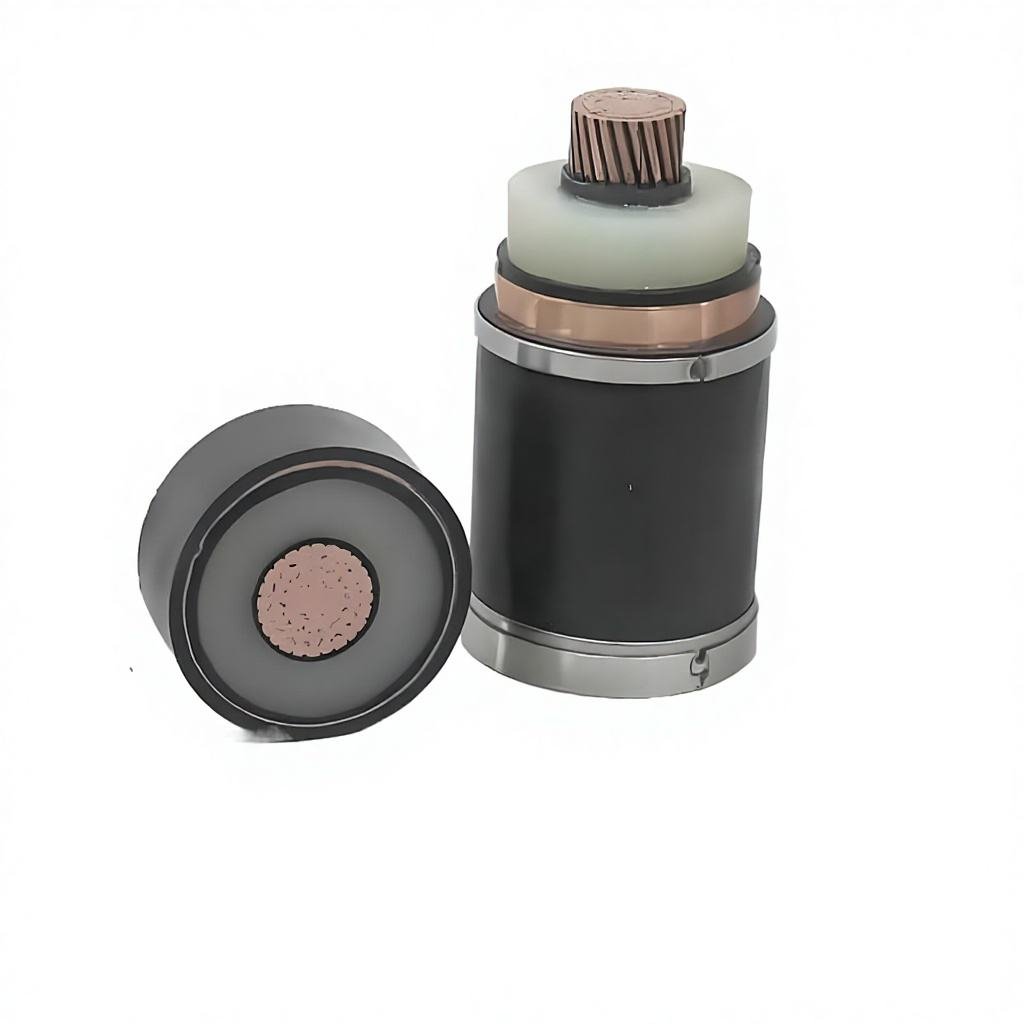
Sheath and material choices follow the installation. Armoured MV cable handles the buried collection circuits, which is the case covered by the 33 kV XLPE cable and 11 kV XLPE cable pages; the general medium and high voltage cable range sets out the conductor, screen and sheath options available across these classes. Inside inverter stations and control buildings, LSZH control cable is the usual companion to the power circuits, and mineral insulated fire resistant cable is specified where circuits must keep operating during a fire — typically emergency shutdown, fire pump and alarm circuits in the substation building.
§03 — FAQ
Questions asked in renewable cable tenders
Why is 33 kV the common choice for wind collection?
It carries more power per circuit over the long distances typical of wind layouts, which reduces the number of switchgear bays at the substation. Small sites with short runs often stay at 20 kV, where the equipment is cheaper.
Do solar collection circuits need UV-resistant sheaths?
Where the cable is fixed to racking or run in open tray, yes. Black polyethylene or a UV-stabilised compound is normally specified, and the route design should avoid continuous exposure where a buried duct is practical.
How is voltage drop budgeted across an array?
Each string is calculated from the inverter terminals to the collection busbar, at peak output, and the result is compared with the grid code and the inverter manufacturer’s operating window. The worst string, not the average, sets the conductor size.
Is armouring required for every buried collection circuit?
On most sites yes, because trench backfill and future excavation risk are unpredictable. The alternative — cable laid in duct with a warning tape and concrete cover — is used where the route is well controlled.