Cable Selection Guide
Cable size cannot be selected from current alone. A safe and economical design also checks voltage drop, installation method, ambient temperature, grouping, short-circuit duty and coordination with protective devices. This guide outlines the data an engineer or buyer should provide.
Quick Answer
Begin with design current and system voltage, then determine the cable ampacity after applying installation and environmental correction factors. Check voltage drop during normal operation and starting conditions, verify short-circuit withstand, and confirm that the protective device will disconnect faults safely. Select the next compliant standard size and document all assumptions.
Step 1: Define the Electrical Load
Record the continuous current, demand factor, load type, power factor, starting current and expected operating profile. Motors, transformers, variable-speed drives and cyclic loads can impose requirements that a simple nameplate-current check misses. Confirm single-phase or three-phase operation, nominal voltage, frequency and whether neutral or harmonic loading affects the selected core arrangement.
Step 2: Describe the Installation
Ampacity changes with installation method. State whether the cable is in air, tray, conduit, duct, direct burial or a thermally insulated space. Include ambient air or soil temperature, soil thermal resistivity, burial depth, number of loaded circuits, spacing and grouping. High ambient temperatures in the Middle East or parts of Africa can reduce allowable current and must not be ignored.
Step 3: Calculate Voltage Drop
Voltage drop depends on conductor resistance, reactance, current, route length and power factor. Long feeders may require a larger conductor even when ampacity is adequate. Check both steady-state operation and equipment starting where relevant. The permitted drop is set by the project design or applicable rules. Parallel runs require equal routing, compatible terminations and proper current sharing.
Step 4: Verify Fault Performance
The conductor and metallic screen, where applicable, must withstand prospective short-circuit energy until the protective device clears the fault. Confirm fault current and clearing time. Protective-device ratings and disconnection requirements must coordinate with cable impedance. Medium-voltage projects also require screen earthing and bonding design.
Step 5: Select Construction and Margin
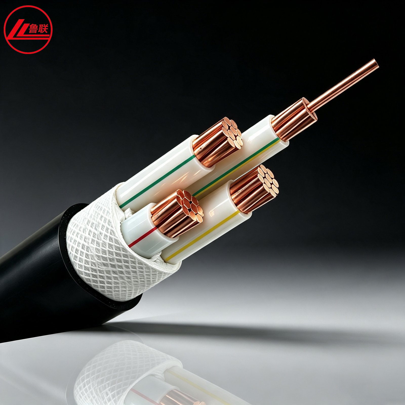
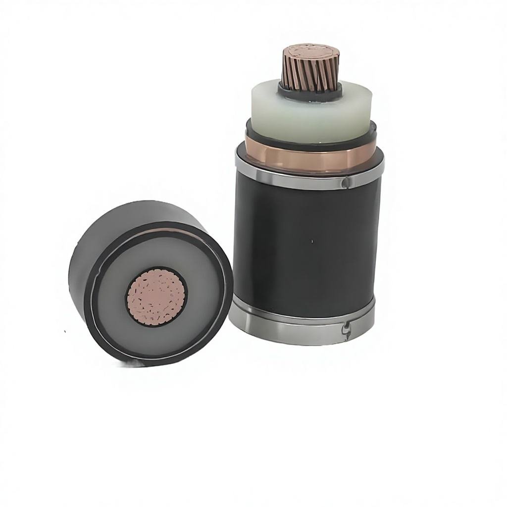
After electrical sizing, choose conductor material, insulation, core count, armour, sheath and fire performance. Consider future load growth without applying arbitrary oversizing that creates cost and installation problems. Check bending radius, pulling tension, drum size, gland range and terminal capacity. For guidance on available constructions, visit our power cable range.
Information to Send for an Accurate Quotation
Send the load current or power, voltage, phase, frequency, power factor, route length, allowable voltage drop, installation method, ambient conditions, grouping, soil data if buried, fault current and clearing time, conductor material, core count, insulation, armour, fire requirement, standard and destination.
Frequently Asked Questions
Can an online cable-size chart replace engineering calculations?
No. Charts use assumptions that may not match your installation, ambient temperature, grouping, route length or fault level.
Should I always choose the next much larger size?
Select a compliant standard size with appropriate design margin. Excessive oversizing can increase cost, bending difficulty and termination requirements.
Who should approve the final size?
A qualified project engineer should approve the design using the applicable electrical rules, protection study and manufacturer data.
Discuss Your Cable Requirement
Lulian Cable supports distributors, contractors, utilities and industrial buyers across Europe, the Middle East and Africa, including Nigeria. Final construction, standards and performance are confirmed in the approved quotation and technical data sheet.